Published by John Coonrod
先进电子解决方案
Rogers Advanced Connectivity Solutions (ACS) has introduced an updated design program that is free to download called the MWI-2017 Microwave Impedance Calculator, a transmission line modeling tool for electronics engineers (setting up an account is required).
MWI-2017 微波阻抗计算器软件不能替代精密的建模工具套件,例如 Agilent Technologies 的 Advanced Design System (ADS) 或 AWR 的 Microwave Office。其预测功能也无法超越平面或 3D 电磁 (EM) 模拟器,例如 Ansys 的 HFSS 或 Sonnet Software 的 Sonnet 套件。不过,这款计算器软件有着自己的专长,即计算最常见的微波传输线的关键参数,包括微带线、带状线和共面波导传输线的关键参数。The software is downloaded as an executable (.exe) file and runs on most Windows-based personal computers, including those with Windows XP, Windows 7 and Windows 10 operating systems. To speed and simplify the use of the software, Rogers also offers a 22-page operator’s manual in PDF file format.
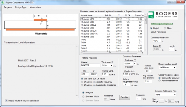
The MWI-2017 program is based on closed-form equations derived from Poisson’s wave equations. The simple-to-use software can determine key parameters for a selected transmission-line type and laminate material, such as the conductor width and conductor metal thickness needed to achieve given impedance at a target frequency. The software’s intuitive graphical user interface (GUI) screen allows a user to select from a variety of different transmission-line types, including conventional microstrip, edge-coupled microstrip, conventional stripline, offset stripline, and conductor-backed coplanar-waveguide (CPCPW) transmission lines. The on-screen menus allow a user to select a transmission-line technology and a laminate material. Once a material, such as Rogers RO3003™ material, is selected, its pertinent characteristics are also shown on the screen, including relative dielectric constant (permittivity), dissipation factor (loss), thermal conductivity, and thermal coefficient of dielectric constant. Moving a mouse cursor over any material name reveals additional information about the material.
With a material in place, the next step is to pick a standard dielectric thickness from a menu, or enter a custom thickness. A standard copper cladding thickness must also be selected from a menu, or a custom thickness entered manually. Copper conductor roughness is also accounted for, either selected from a menu as a standard value, or entered manually as a nonstandard value. Similarly, a standard value for copper conductivity can be used in a calculation, or a custom value entered, although any change in the value for copper conductivity will affect all metal layers in a multilayer circuit.
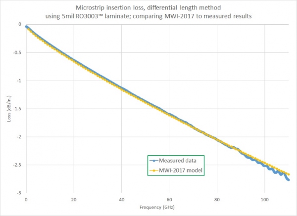
The MWI-2017 software allows an operator to enter parameters pertinent to a specific application, such as operating frequency and RF power level. Once a user has selected the desired transmission-line type, dielectric material, material thickness, conductor width, thickness of the conductive metal cladding, etc., a calculation will provide results in terms of such transmission-line parameters as conductor width and conductor spacing for a selected impedance. The software can generate insertion loss tables of data that can be used to create plots of loss versus frequency, and these plots can then be compared to actual measured results from a microwave vector network analyzer (VNA).
This exact procedure was performed to evaluate the accuracy of the MWI-2017 software for calculations of conventional microstrip parameters. MWI-2017 calculations performed for conventional microstrip transmission lines have proven to be extremely accurate since they include the effects of dispersion as well as copper roughness. For example, calculations performed on RO3003™ laminates have compared quite closely with actual measurements. These are ceramic-filled PTFE composite materials with a dielectric constant of 3.0 at 10 GHz and dissipation factor of 0.0010 at 10 GHz. In a comparison of MWI-2017 predictions versus measurements for a 5-mil-thick microstrip transmission line on RO3003 laminate with 1/2-oz. ED copper cladding, predicted and measured data matched almost exactly through 110 GHz.
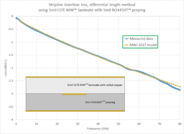
The MWI-2017 software may not be able to match the accuracy of an EM simulator for a given prediction, but it is considerably faster, providing results almost instantaneously. It has been found to be most accurate for calculations on conventional microstrip and stripline, very accurate with edge-coupled microstrip and offset stripline transmission lines, and fairly accurate with conductor-backed coplanar-waveguide (CBCPW) transmission lines, although in the case of CBCPW transmission lines, vias must be properly placed to ensure accurate results.
Calculating the impedance of transmission lines is not trivial, since a number of factors can affect impedance. In microstrip, the width of the conductor and thickness of the dielectric substrate impact impedance. In CBCPW, not only the conductor width and dielectric thickness, but the spacing on the signal plane between the signal conductor and the adjacent ground planes will affect impedance. The MWI-2017 software is free, and provides results fairly quickly that are accurate and can be saved for use in other programs, including in word processors or in spreadsheets for creating x-y plots. In addition to calculating the impedance and loss of a transmission line, the MWI-2017 software provides information on a laminate’s effective dielectric constant, signal wavelength, skin depth, the electric length for a transmission line at a selected frequency, and propagation delay. It can even calculate the temperature rise above ambient temperature for a selected laminate based on an input RF power level.
For anyone needing a quick impedance calculation for designing a filter, coupler, or other high-frequency circuit, the MWI-2017 software provides usable results. And the price is right!
发布于 2018 年 7 月 12 日